The Hardware Platform
Physical Setup
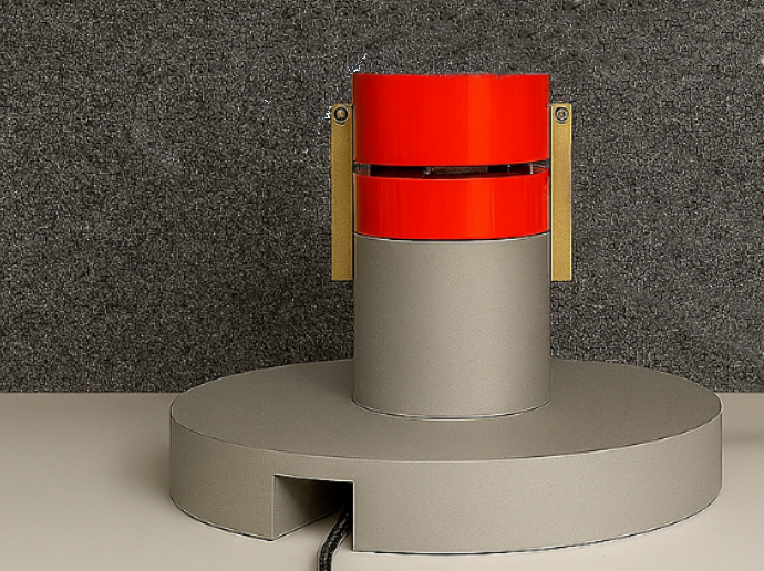
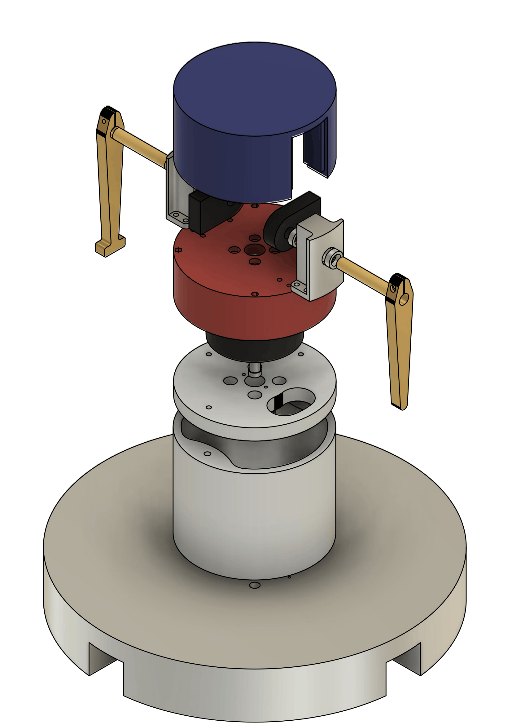
The platform consists of a rigidly mounted base carrying a direct-drive rotating arm. One or more pendulum links hang from the arm tip, each connected at its pivot via a low-friction ball bearing and instrumented with an incremental optical encoder. The reference configuration documented here uses two pendulum links; the firmware supports one and two links, and the mechanical design accommodates up to four through a firmware extension only, with no change to the motor, base, or arm.
A hollow-bore rotor shaft routes power and signal lines through a slip ring, enabling unbounded continuous arm rotation, which is a prerequisite for swing-up manoeuvres that require multiple full turns.
Layered Architecture
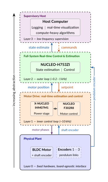
The system is organised as a four-layer vertical stack of increasing abstraction:
| Layer | Role | Hardware | Rate |
|---|---|---|---|
| 0 | Physical Plant | Motor, encoders, pendulum links | n/a |
| 1 | Motor Drive (FOC) | NUCLEO-F302R8 (Cortex-M4, 72 MHz) | ~10 kHz |
| 2 | State Estimation and Control | NUCLEO-H753ZI (Cortex-M7, 480 MHz) | 0.2–1 kHz |
| 3 | Supervisory Host | PC | Low frequency |
Each layer communicates with its neighbours through a narrow, contractual interface. This means any layer can be replaced by an alternative implementation: VESC or ODrive at Layer 1, a Teensy 4.1 or Raspberry Pi at Layer 2, without modifying the rest of the stack.
A key architectural decision is that pendulum encoders bypass Layer 1 entirely and connect directly to Layer 2. This cleanly separates the motor-commutation problem (which requires only the shaft angle) from the system-level estimation and control problem (which requires all joint angles), and prevents the motor controller timing from becoming a bottleneck for the outer loop.
Components
The platform is assembled from commercially available, off-the-shelf parts:
| Component | Part / Supplier |
|---|---|
| BLDC motor | GB54-2 / T-Motor |
| Power stage | X-NUCLEO-IHM07M1 / STMicroelectronics |
| Motor-control MCU | NUCLEO-F302R8 / STMicroelectronics |
| Encoders (x3) | HEDM-5500#B13 / Broadcom |
| Main controller | NUCLEO-H753ZI / STMicroelectronics |
The motor-shaft encoder serves a dual role: it provides the electrical rotor angle for Field-Oriented Control and, because the rotor is directly coupled to the arm without a gearbox, simultaneously measures the arm angle for the outer control loop. With 4x quadrature decoding of the 1000 CPR encoder on a 14-pole motor, this gives a mechanical resolution of 0.09° per count.